Are you planning to build or renovate a structure but feeling a bit confused by all the various drawings that are being presented? Don't worry, you're not alone! Architectural and structural drawings may seem overwhelming but they are quite easy to read and understand.
Architectural and structural drawings are two types of technical drawings used in construction projects, but they serve different purposes and are created by different professionals. Architectural drawings focus on the design and functionality of a building, On the other hand, structural drawings are created by engineers specializing in structural design, which focuses on the strength and stability of a building's framework. In this article, we will compare the two types of drawings based on common themes to help you better understand their role in your construction project. Let’s take a look at the key differences between architectural and structural drawings.
Who creates architectural and engineering drawings?
Architects are responsible for creating architectural drawings. Preliminarily, architects create early-stage drawings that are primarily intended to convey design ideas. These drawings serve as a way to communicate conceptual ideas and options effectively. During the early stages of the process, project owners review multiple sets of interior and exterior building drawings. Ultimately, approving a design to move on to the project's next phase.
Architectural drawings are also shared with other team members, including engineers and contractors, to develop engineering drawings and create a cohesive picture of what the structure should look like when it's complete. The accuracy and clarity of these drawings are crucial to ensure that the final structure meets the client's expectations.
Engineering drawings are an essential aspect of any construction project. They are created by engineers who specialize in fields such as structural, electrical, and mechanical engineering. These drawings contain technical specifications that are used to guide the construction process.
In addition to engineering drawings, contractors generate shop drawings for prefabricated pieces. These drawings are essential for off-site work that needs to be performed before the project begins. Contractors use shop drawings to communicate the precise specifications of the prefabricated parts, ensuring that the parts are made as per the requirement for the construction project.
Engineering drawings are used throughout the design and construction process. While project owners may view these drawings, they are mainly used as construction drawings by the general contractors and construction teams who physically build the structure. These drawings provide detailed information on the design specifications, materials, and construction techniques required to build the structure.
Type of presentation/ visual identification
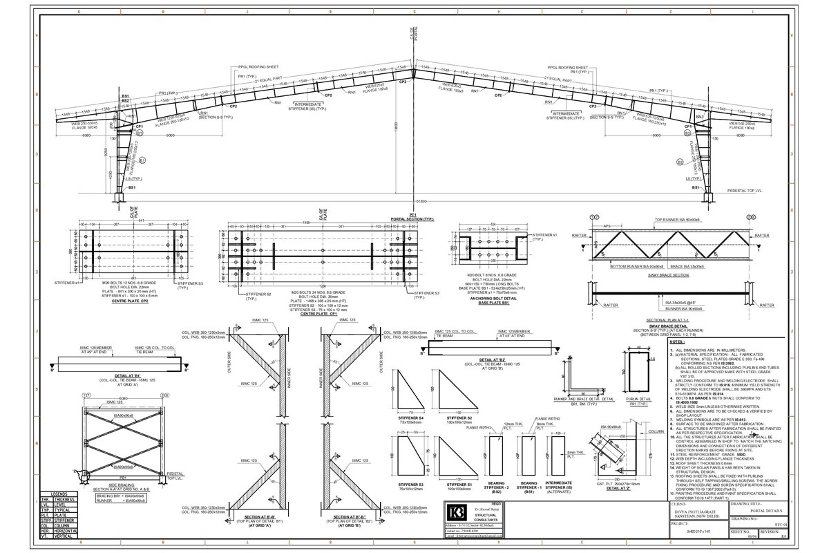
Structural engineering drawings are mostly line work drawings, emphasizing the structural elements and details. They provide a detailed technical representation of a product or system, conveying specific information required for construction or manufacturing.
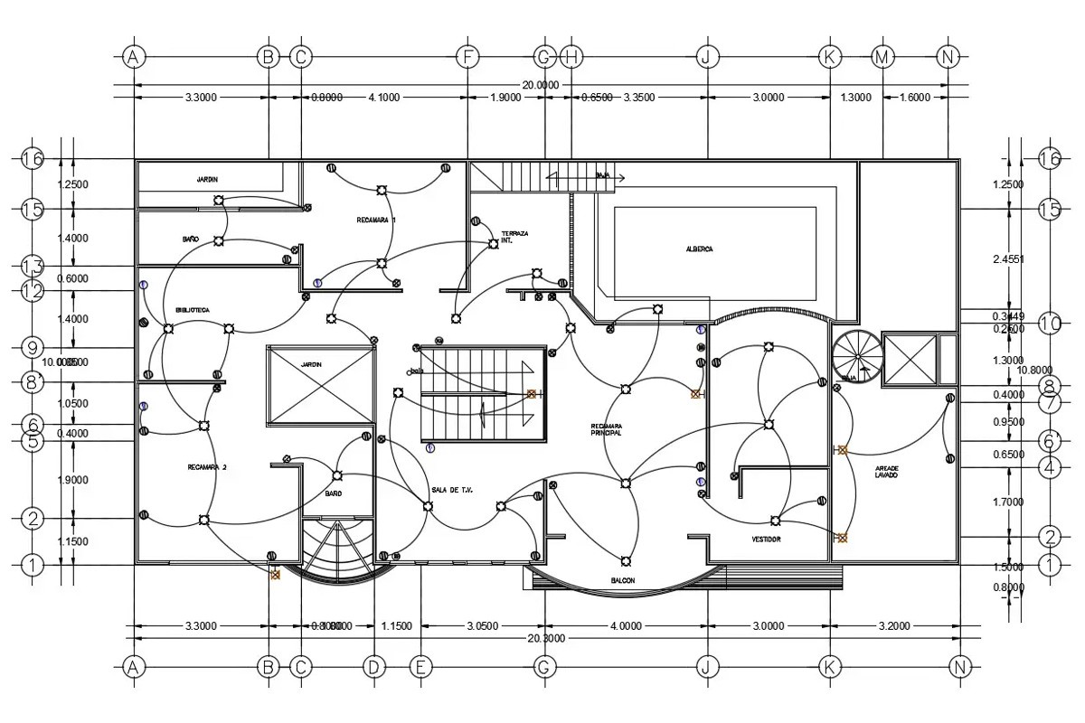
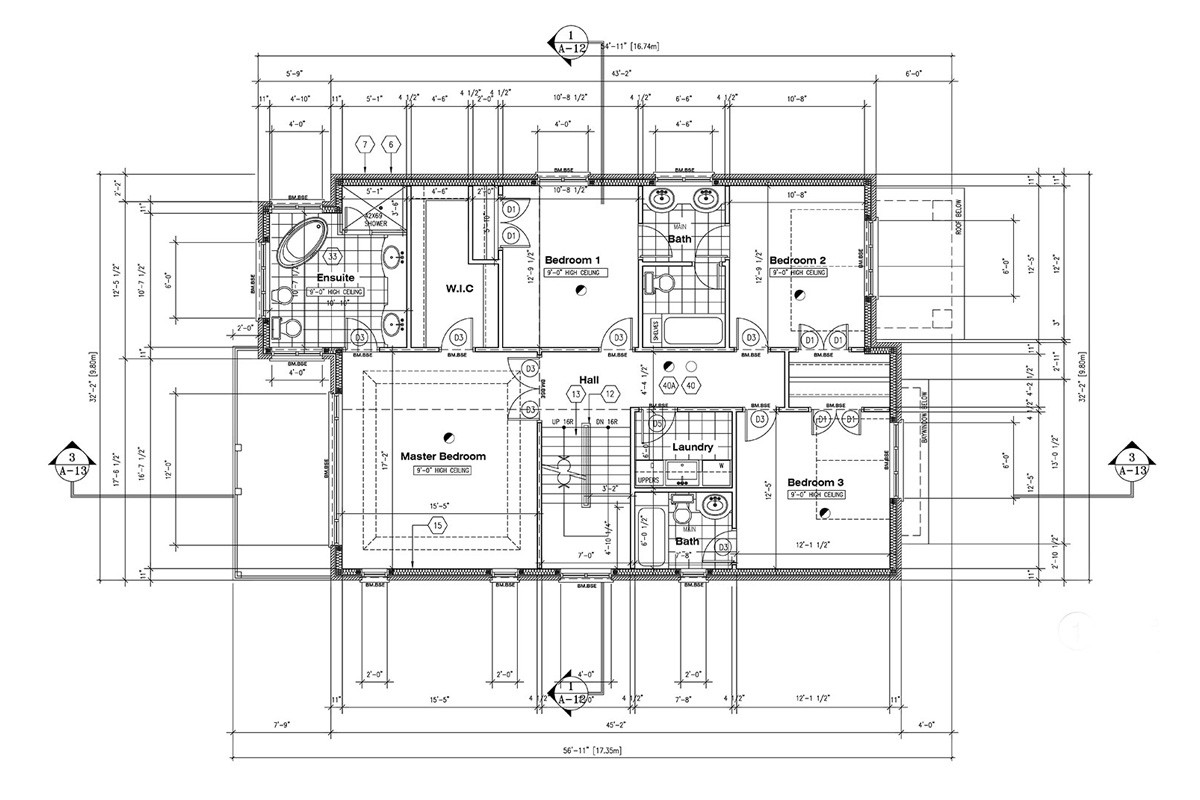
On the other hand, architectural drawings focus more on the overall design and aesthetics of the building, showcasing elements like walls, windows, doors, and other architectural features. Architectural drawings are generally more detailed and can include elements like furniture layout and other interior details as well.
Typology of drawings and their content
Architectural Drawings:
As part of the design process, architects come up with creative design ideas that are uniquely tailored to the client's requirements and are responsive to the climatic and site conditions. These include a series of detailed drawings that capture what the building will look like on the inside as well as outside which depends on many factors such as the functionality of the building. Architectural drawings include:
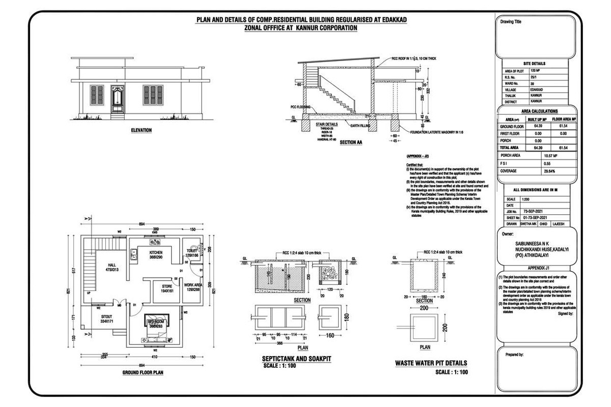
• Site plans
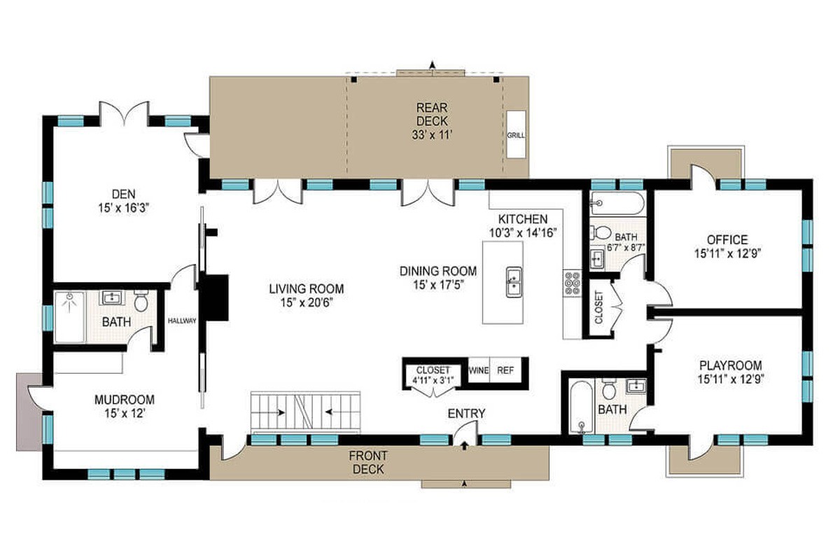
• Floor plans
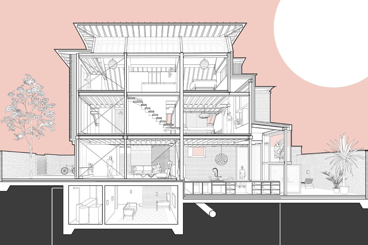
• Cross-section drawings
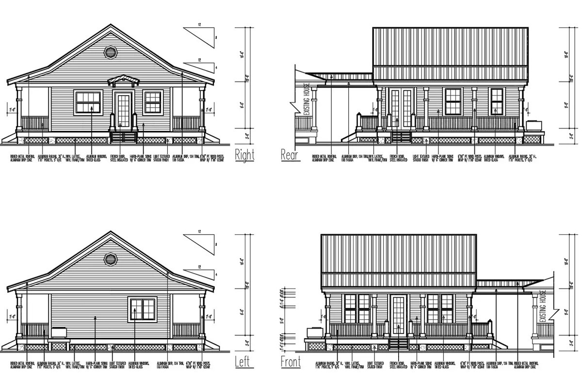
• Elevations
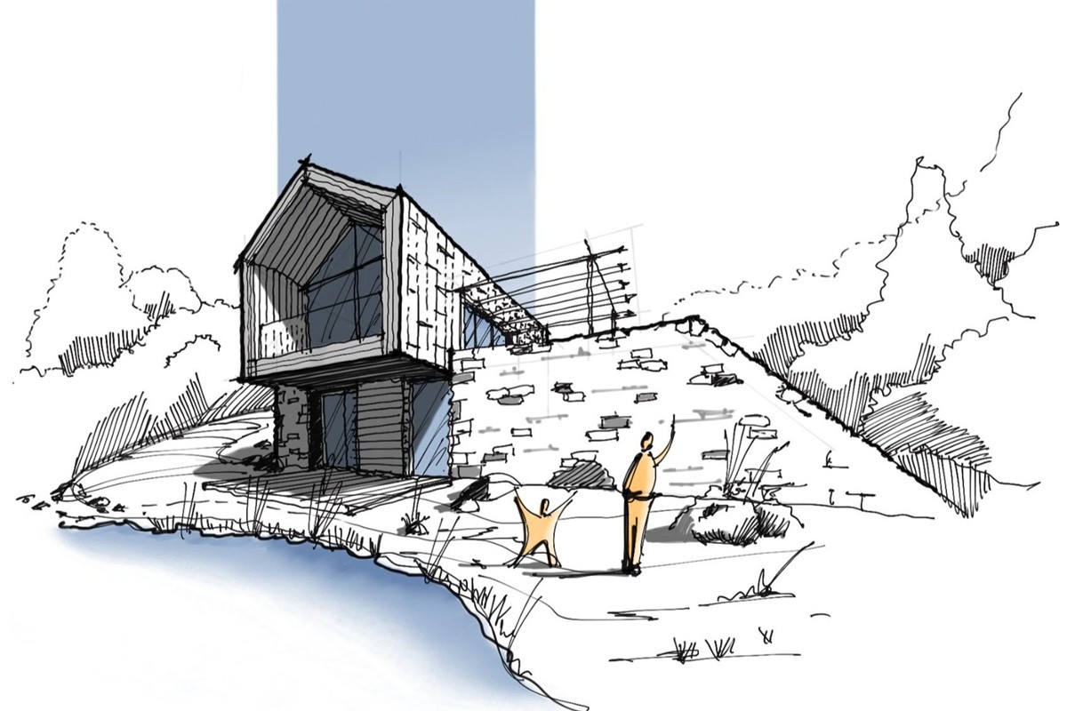
• Perspective drawings
• Renderings
Let us understand the purpose of each of these drawings: